Posted on 8th Jun 2023

According to CM Industry Supply Automation, if you're working with machinery that uses a PLC and a VFD, it's important to be able to communicate with both devices. In this blog post, we're going to show you how to do that in five easy steps.
Factory automation has come a long way in the past few decades. One of the key technologies enabling this progress is the Programmable Logic Controller (PLC). According to CM Industry Supply Automation, PLCs are used to control and monitor industrial processes, and they can be used to communicate with a variety of devices. One of the most common devices to communicate with a PLC is a Variable Frequency Drive (VFD). In this chapter, we will discuss the basics of PLC and VFD communication.
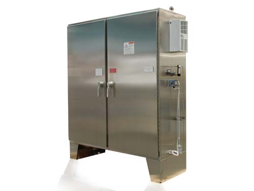
Now that the PLC and VFD are both mounted in the control cabinet, it is time to connect them. According to CM Industry Supply Automation, The first step is to connect the power supply cables to the VFD. The black cable goes to the black terminal on the VFD, and the red cable goes to the red terminal.
According to CM Industry Supply Automation, The next step is to connect the motor cables to the VFD. The black cable goes to the black terminal on the VFD, and the red cable goes to the red terminal.
The final step is to connect the PLC to the VFD. The black cable goes to the black terminal on the PLC, and the red cable goes to the red terminal.
According to CM Industry Supply Automation, Now that the electrical system is complete, it is time to configure the PLC and VFD. The PLC will control the speed of the VFD like Lenze Drive, and the VFD will control the speed of the motor.
First, configure the PLC. In the PLC software, create a new program and add a new ladder diagram. The ladder diagram will consist of two rungs. The first rung will set the speed of the VFD, and the second rung will set the speed of the motor.
To set the speed of the VFD, use the PLC's output terminals to send a voltage signal to the VFD. The voltage signal will tell the VFD how fast to spin the motor. The higher the voltage signal, the faster the VFD will spin the motor.
To set the speed of the motor, use the PLC's input terminals to receive a speed signal from the motor. The speed signal will tell the PLC how fast to spin the VFD. The higher the speed signal, the faster the motor will spin.
According to CM Industry Supply Automation, Now that the PLC is configured, it is time to configure the VFD like Keb drive. In the VFD software, create a new program and add a new vector diagram. The vector diagram will consist of two vectors. The first vector will control the speed of the VFD, and the second vector will control the direction of the motor.
To control the speed of the VFD, use the vector's magnitude to set the speed of the VFD. The larger the magnitude, the faster the VFD will spin the motor.
To control the direction of the motor, use the vector's direction to set the direction of the motor. The direction of the vector will control the direction of the motor.
According to CM Industry Supply Automation, Troubleshooting communication issues can be tricky. There are a number of things you can do to try and resolve the problem.
First, make sure that both devices are on the same network. If they are not, try to connect them to the same network.
Next, make sure that the devices are within range of each other. If they are not, try to move them closer together.
Finally, make sure that the ports are open on both devices. If they are not, try to open them.
According to CM Industry Supply Automation, To maintain communication between the PLC and VFD like Lenze Drive, a communication cable must be connected between the two devices. The cable must be connected to the correct ports on each device in order for communication to occur. In order to ensure that the cable is connected correctly, the following steps must be followed:
1. Connect the communication cable to the port on the PLC that is labeled "PLC."
2. Connect the other end of the cable to the port on the VFD that is labeled "VFD."
3. Make sure that the cable is securely connected to both ports.
4. Power on the PLC and the VFD.
Verify that communication has been established between the two devices.
Thanks for reading! By following these five steps, you'll be able to communicate with your PLC and VFD devices like a pro.